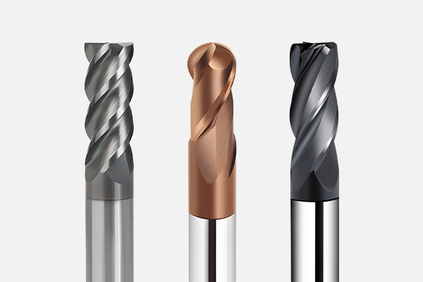
The helix angle (Helix Angle) is a critical geometric feature that determines a tool’s cutting performance, directly influencing cutting forces, chip evacuation efficiency, and tool life. For manufacturers exporting carbide tools, mastering helix angle optimization strategies is the key to technological competitiveness for winning overseas clients. This article delves into the design logic and application scenarios of helix angles, helping you provide cost-saving and efficiency-boosting tool solutions for customers.
I. Three Major Design Dimensions of Helix Angle
1. Angle Range and Material Compatibility
- 30°–45° Standard Helix Angle: Balances rigidity and sharpness, suitable for general steel machining (e.g., carbon steel, alloy steel).
- 45° High-Performance Helix Angle: Reduces radial forces, designed for stainless steel, titanium alloys, and other difficult-to-machine materials to minimize vibration risks.
- 60° Extra-Large Helix Angle: Targets high-hardness materials (e.g., hardened steel above HRC50), enabling efficient heat dissipation by extending chip contact paths.

2. Dynamic Variation and Structural Innovation
- Drill Bit Gradient Helix Design: 25°–32° at the outer edge ensures sharpness, while reducing to 6° near the core enhances rigidity, minimizing drill breakage risks.
- Variable Helix Angle Technology: Utilizes 30°–45° progressive angles or unequal tooth spacing to suppress harmonic resonance, improving stability for thin-wall part machining.
Case Study:
“A German automotive parts manufacturer achieved a 40% increase in efficiency and surface roughness Ra <0.8μm for aluminum alloy housings after adopting our variable helix angle end mills.”
3. Rotation Direction and Chip Evacuation Strategy
- Right-Hand Helix Angle (Mainstream design): Aligns with clockwise spindle rotation for upward chip evacuation, preventing chip accumulation in deep-cavity machining.
- Left-Hand Helix Angle: Specifically for blind-hole machining, avoiding chip clogging at the workpiece bottom.
II. Four Major Commercial Benefits of Helix Angle Optimization
- Reduced Per-Part Machining CostsLarge helix angles lower cutting resistance, reducing spindle load by 15%–20% and extending tool life by over 30%.
- Overcoming Challenges in Difficult-to-Machine MaterialsFor high-temperature alloys (e.g., Inconel 718), a 60° helix angle design promotes finer chip curling, increasing breakage rates by 65% and eliminating chip entanglement-induced surface scratches.
- Improved Precision Machining Yield
- 30° Small Helix Angle: Minimizes axial deformation in thin-wall parts, maintaining tolerances within ±0.01mm.
- 45° Medium Helix Angle: Optimizes vertical surface machining for mold steel, achieving perpendicularity errors <0.02mm/100mm.
- Tailored for Automated Production LinesVariable helix angle designs reduce tool vibration by up to 50%, meeting the high standards of unmanned machining centers for stable, unattended operations.
III. Quick Selection Guide: Helix Angle Recommendations by Material
1. Aluminum/Copper Alloys (Lightweight, High-Ductility Materials)
- Recommended Helix Angle: 45°–60°
- Applications: High-speed milling (≥10,000 rpm) for 3C product housings, heat sinks, and connectors.
- Optimization Tips:
- Large angles reduce cutting resistance and improve surface finish.
- Pair with sharp edges (15°–20° rake angle) and polished flute designs to minimize burrs.
- Example tool: 3-flute aluminum-specific end mills with PCD coating or uncoated ultra-fine carbide.
2. Carbon Steel/Cast Iron (Medium Hardness, Batch Machining)
- Recommended Helix Angle: 30°–40°
- Applications: Engine blocks, transmission housings, and hydraulic valves at 2,000–6,000 rpm.
- Optimization Tips:
- Medium angles balance cutting forces and tool rigidity for heavy-depth cuts (ap ≤0.5×D).
- Use 10°–20° rake angles and TiAlN coatings for cast iron to resist abrasive wear.
- Example tool: 5–6-flute high-density end mills with chip breakers.
3. Hardened Steel (HRC50+, High Hardness)
- Recommended Helix Angle: ≤30° (typically 20°–25°)
- Applications: Precision machining of mold cavities and stamping dies (1,000–3,000 rpm).
- Optimization Tips:
- Small angles enhance edge strength for interrupted cuts.
- Negative rake angles (-5° to -10°) and rigid clamping prevent chatter marks.
- Example tool: 4-flute corner-radius end mills with AlCrN/TiSiN coatings.
4. Titanium Alloys (Low Thermal Conductivity, Work-Hardening)
- Recommended Helix Angle: 35°–45° (45° common in aerospace)
- Applications: Jet engine blades, aircraft structures, and medical implants.
- Optimization Tips:
- Medium-to-large angles reduce heat buildup and work-hardening.
- Mandatory high-pressure coolant (≥70 bar) and low speeds (vc=30–60 m/min).
- Example tool: 2–3-flute roughing end mills with honed edges and TiAlCrN coatings.
5. Other Materials
- Stainless Steel (Austenitic/Duplex): 40°–50° with high-toughness substrates (e.g., ultra-fine carbide).
- High-Temp Alloys (Inconel): 30°–35° with heat-resistant coatings (e.g., diamond).
- Composites (CFRP): 10°–20° with specialized edges to prevent delamination.
Core Selection Logic:
- Material Hardness ↑ → Helix Angle ↓ (prioritize rigidity)
- Cutting Speed ↑ → Helix Angle ↑ (reduce heat)
- Interrupted Cuts → Helix Angle ↓ (resist impact)
- Thin-Wall/Long Overhang → Helix Angle ↑ (lower radial forces)
Contact Us for Expert Guidance on Helix Angle Optimization
If you’re looking to enhance your machining efficiency, reduce costs, or tackle challenging materials, our team of experts is here to help. Whether you need tailored recommendations for your specific application or advanced tooling solutions, we’ve got you covered.
? Email Us: sdfgroup@sdftools.com
? Connect on LinkedIn: Your Company LinkedIn Profile
Let’s collaborate to optimize your cutting processes and achieve superior results!

